Enhanced TDS
Identification & Functionality
- Chemical Family
- Fillers Included
- RTU Product Type
- Technologies
- Product Families
Features & Benefits
- Ready-to-Use Product Features
- Key Properties
- Very high mechanical and electrical properties
- Very high thermal shock resistance
Applications & Uses
- Compatible Substrates & Surfaces
- Composites Processing Methods
- Cure Method
- Product End Uses
- Markets
- Applications
- Remarks
Because both products contain accelerating additives, avoid storing them for extended periods at elevated temperatures. Correct handling of the components can result in undesirable viscosity increase, change in reactivity and substandard cured-state properties.
- Application Information
- Indoor electrical insulators for medium and high voltage, such as switch and apparatus components, bushings, instrument transformers and power transformers.
- Encapsulation of large metal components.
- Processing Methods
- Automatic pressure gelation process (APG)
- Conventional gravity casting process under vacuum
Properties
- Physical Form
- Processing Viscosities
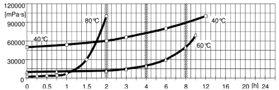
Fig.4.1: Viscosity increase at 40, 60 and 80°C (measurements with Rheomat 115)
(Shear rate D = 10 s-1)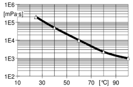
Fig.4.2: Initial viscosity as a function of temperature
(measurements with Rheomat 115, D =10 s-1)- Processing Viscosities
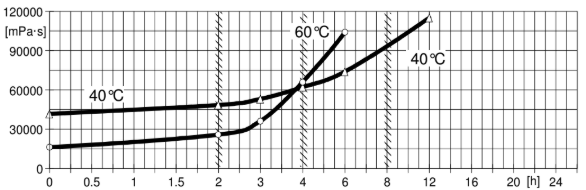
Fig.4.1: Viscosity increase at 40 and 60°C (measurements with Rheomat 115)
(Shear rate D = 10 s-1)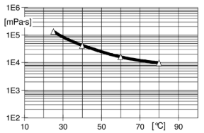
Fig.4.2: Initial viscosity as a function of temperature
(measurements with Rheomat 115, D =10 s-1)
Regulatory & Compliance
- Certifications & Compliance
Technical Details & Test Data
- Specific Instructions
The effective pot-life of the mix is about 2 days at temperatures below 25°C. Conventional batch mixers should be cleaned once a week or at the end of work. For longer interruptions of work, the pipes of the mixing and metering installations have to be cooled and cleaned with the resin component to prevent sedimentation and/or undesired viscosity increase. Interruptions over a week-end (approx. 48h) without cleaning are possible if the pipes are cooled at temperatures below 18°C.For data on viscosity increase and gel time at various temperatures, refer to Figs: 4.1 and 4.4.
Mould temperature
APG process : 130 - 160°C
Conventional vacuum casting : 70 - 100°C
Demoulding times (depending on mould temperature and casting volume)
APG process : 10 - 40 min
Conventional vacuum casting : 5 - 8h
Cure conditions : (minimal postcure)
APG process : 4h at 130°C or 3h at 140°C
Conventional vacuum casting : 12h at 130°C or 8h at 140°CTo determine whether crosslinking has been carried to completion and the final properties are optimal, it is necessary to carry out relevant measurements on the actual object or to measure the glass transition temperature. Different gelling and curecycles in the manufacturing process could lead to a different crosslinking and glass transition tempe- rature respectively.
- Gelation / Cure Time
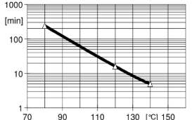
Fig.4.4: Geltime as a function of temperature
(measured with Gelnorm Instrument, ISO 9396)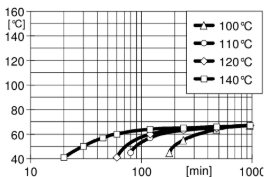
Fig.4.5: Glass transition temperature as a function od the cure time
(isothermic reaction, IEC 61006)- Special Properties
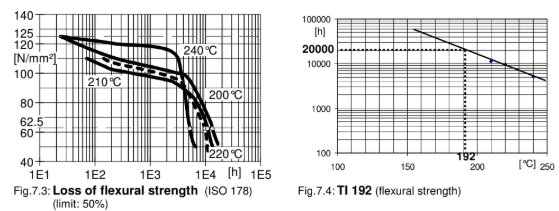
Thermal Endurance
Profile acc. IEC 60216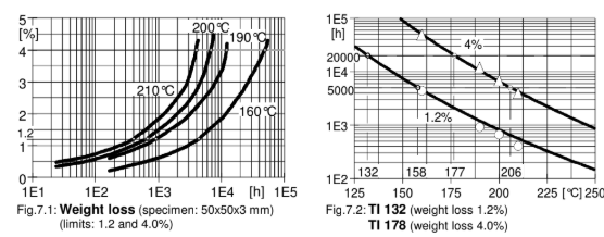
Thermal shock resistance
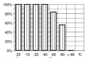
Fig.7.5: Crack resistance / Temperature shock test
Passed specimen (%) in function of the temperature steps
Mean failure temperature: - 88°C
Embedded metal parts with edge radius of 2 mm- Electrical Properties
System tested:
Araldite CY 205 IN / HY 905 IN / DY 040 / DY 061 / Silica.
Mix ratio: 100 / 100 / 10 / 1 / 410.
Determined on standard test specimen at 23°C.
Cured for 6h at 80°C + 10h at 130°C.Property
Test Method
Unit
Value Range
Breakdown strength
IEC 60243-1
kV/mm
18 - 22
Breakdown strength (embedded Rogowski electrodes)
Huntsman method
kV/mm
36 - 41
Diffusion breakdown strength
DIN/VDE 0441/1
class
HD 2
Temperature of specimen after test
-
°C
23
HV arc resistance
IEC 61621
s
185 - 195
Tracking resistance (with test solution A)
-
CTI
> 600-0.0
Tracking resistance (with test solution B)
-
CTI
> 600M-0.0
Electrolytic corrosion
IEC 60426
grade
A-1
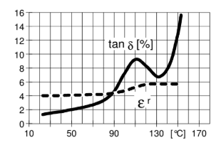
Fig.6.1: Loss factor (tan δ) and dielectric constant (εr) as a function of temperature measurement frequency: 50 Hz, IEC 60250/ DIN 53483)
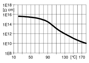
Fig.6.2: Volume resistivity (ρ) versus function of temperature (measurement voltage: 1000 V, IEC 60093/ DIN 53482)
- Mechanical & Physical Properties
Araldite CY 205 IN / HY 905 IN / DY 040 / DY 061 / Silica.
Mix ratio: 100 / 100 / 10 / 1 / 410, cured for 6h at 80°C + 10h at 130°C.Determined on standard test specimen at 23°C.
Property
Test Method
Unit
Value Range
Tensile strength
ISO 527
MPa
75 - 85
Elongation at break
ISO 527
%
0.9 - 1.1
E modulus from tensile test
ISO 527
MPa
12000 - 13000
Flexural strength
ISO 178
MPa
125 - 135
Surface strain
ISO 178
%
1.1 - 1.5
E modulus from flexural test
ISO 178
MPa
11600 - 12000
Compressive strength
ISO 604
MPa
140 - 150
Compression set
ISO 604
%
6 - 7
Impact strength
ISO 179
kJ/m²
10 - 12
Double Torsion Test
CG 216-0/89
-
-
Critical stress intensity factor (K1C)
-
MPa·m½
2.7 - 2.9
Specific energy at break (G1C)
-
J/m²
570 - 620
Martens temperature
DIN 53458
°C
80 - 90
Glass transition temperature (DSC)
ISO 11357-2
°C
85 - 95
Coefficient of linear thermal expansion
ISO 11359-2
K⁻¹
31 - 36·10⁻⁶
Thermal conductivity
ISO 8894-1
W/mK
0.8 - 0.9
Glow resistance
DIN 53459
class
2b
Flammability
UL 94
class
HB, V1
Thermal endurance profile (TEP)
IEC 60216
-
Fig. 7.1 - 7.2
Temperature index (TI)
-
°C
164 / 187
Thermal ageing class (20000h)
IEC 60085
class
F
Water absorption (specimen: 50x50x4 mm)
IEC 60062
% by wt.
0.10 - 0.20
Decomposition temperature
DTA
°C
> 350
Density (Filler load: 66 % by wt.)
ISO 1183
g/cm³
1.80 - 1.90
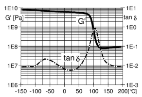
Fig.5.1: Shear modulus (G') and mechanical loss-factor (tan δ) as a function of temperature (measured at 1 Hz.)
(ISO 6721-7, method C)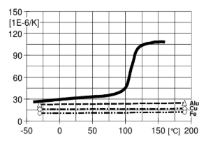
Fig.5.2: Coefficient of linear thermal expansion (α) as a function of temperature (ISO 11359-2, reference temperature: 23°C)
- Electrical Properties
Determined on standard test specimen at 23°C
Cured for 6h at 80°C + 10h at 130°CProperty
Test Method
Unit
Value
Breakdown strength (3 mm plates)
IEC 60243-1
kV/mm
18-20
Breakdown strength (embedded Rogowski)
Huntsman
kV/mm
32-38
Diffusion breakdown strength
DIN VDE 0441-1
class
HD 2
Temperature of specimen after test
-
°C
25-31
HV arc resistance
IEC 61621
s
181-185
Tracking resistance (test solution A)
IEC 60112
CTI
>600.0
Tracking resistance (test solution B)
IEC 60112
CTI
>600.0
Electrolytic corrosion
IEC 60426
grade
A-1
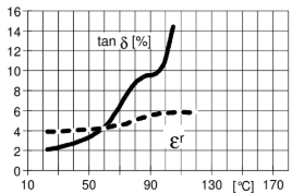
Fig.6.1: Loss factor (tan δ) and dielectric constant (εr) as a function of temperature
(measurement frequency: 50 Hz, IEC 60250)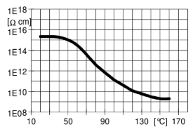
Fig.6.2: Volume resistivity (ρ) as a function of temperature
(measurement voltage: 1000 V, IEC 60093)- Mechanical & Physical Properties
Determined on standard test specimen at 23°C
Cured for 6h at 80°C + 10h at 130°CProperty
Test Method
Unit
Value
Tensile strength
ISO 527
MPa
70-80
Elongation at break
ISO 527
%
2.0 - 2.5
E modulus from tensile test
ISO 527
MPa
9400-10400
Flexural strength
ISO 178
MPa
135-145
Surface strain
ISO 178
%
18-22
E modulus from flexural test
ISO 178
MPa
9700-10200
Compressive strength
ISO 604
MPa
120-130
Impact strength
ISO 179
kJ/m²
11-13
Double Torsion Test
CG 216-0/89
-
-
Critical stress intensity factor (Kic)
-
MPa·m¹/₂
2.8 - 3.2
Specific energy at break (Gic)
-
J/m²
850 - 950
Martens temperature
DIN 53458
°C
60-65
Heat distortion temperature
ISO 75
°C
65-70
Glass transition temperature (DSC)
ISO 11357-2
°C
60-70
Coefficient of linear thermal expansion
ISO 11359-2
K⁻¹
41 - 46×10⁻⁶
Thermal conductivity similar to
ISO 8894-1
W/mK
0.8 - 0.9
Glow resistance
IEC 60707
class
2b
Flammability
UL 94
class
HB (4mm), V1 (12mm)
Thermal endurance profile (TEP)
DIN/IEC 60216
-
Fig. 7.1-7.4
Water absorption
ISO 62
% by wt.
0.10-0.15 (10 days)
% by wt.
0.30-0.35 (60 min)
Decomposition temperature (heating rate)
DTA
°C
>350
Density (Filler loading: 60% by wt.)
ISO 1183
g/cm³
1.77-1.81
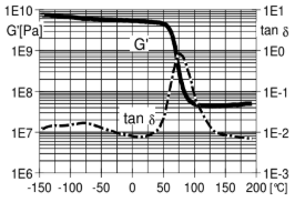
Fig.5.1: Shear modulus (G') and mechanical loss factor (tan δ) as a function of temperature (measured at 1 Hz.)
(ISO 6721, method C)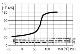
Fig.5.2: Coefficient of linear thermal expansion (α) as a function of temperature
(reference temperature: 23°C, ISO 11359-2)- Special Properties
System tested:
Araldite CY 205 / Aradur HY 905 / DY 040 / DY 061 / Silica
Mix ratio: 100 / 100 / 10 / 1 / 410Thermal Endurance Profile IEC 60216
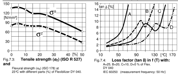
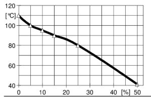
Fig.7.5: Glass transition temperature
Thermal Shock Resistance
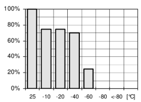
Fig.7.5:Crack resistance / Temperature shock test
Passed specimen (%) as a function of the temperature steps
Mean failure temperature: - 49°C
Embedded metal parts with 2 mm radius- Processing Information
General instructions for preparing liquid resin systems
- Long pot life is desirable in the processing of any casting resin system. Mix all of the components together very thoroughly at room temperature or slightly above and under vacuum. Intensive wetting of the filler is extremely important. Proper mixing will result in:
- better flow properties and reduced tendency to shrinkage
- lower internal stresses and therefore improved mechanical properties on object
- improved partial diskharge behavior in high voltage applications.
- For the mixing of medium- to high viscous casting resin systems and for mixing at lower temperatures, we recommend special degassing mixers that may produce additional selfheating of 10-15 K as a result of friction. For low viscous casting resin sys-tems, conventional mixers are usually sufficient.
- In larger plants, the individual components (resin, hardener) are mixed with the respective quantities of fillers and additives under vacuum. Metering pumps then feed these premixes to the final mixer or a continuous mixer. The individual premixes can be stored at elevated temperature (about 60°C) for up to about 1 week, de-pending on formulation. Intermittent agitation during storage is advisable to prevent filler sedimentation.
- Mixing time can vary from 0.5 to 3 hours, depending on mixing temperature, quantity, mixing equipment and the particular application. The required vacuum is 0.5 to 8 mbar. The vapor pressure of the individual components should be taken into account. In the case of dielectrically highly stressed parts, we recommend checking the quality consistency and predrying of the filler. Their moisture content should be <0.2%.
Specific Instructions
The effective pot-life of the mix is about 2 days at temperatures below 25°C. Conventional batch mixers should be cleaned once a week or at the end of work. For longer interruptions of work, the pipes of the mixing and metering installllations have to be cooled and cleaned with the resin component to prevent sedimentation and/or undesired viscosity increase. Interruptions over a week-end (approx. 48h) without cleaning are possible if the pipes are cooled at temperatures below 18°C. Viscosity increase and gel time at various temperatures.
Mold temperature
APG process: 130 - 160°C
Conventional vacuum casting: 70 - 100°C
Demolding times (depending on mold temperature and casting volume)
APG process: 10 - 40 min
Conventional vacuum casting: 5 - 8 h
Cure conditions
APG process (minimal postcure): 4h at 130°C or 3h at 140°C
Conventional vacuum casting: 12h at 130°C or 8h at 140°C- To determine whether crosslinking has been carried to completion and the final properties are optimal, it is necessary to carry out relevant measurements on the actual object or to measure the glass transition temperature. Different geling and cure cycles in the manufacturing process could lead to a different crosslinking and glass transition temperature
respectively
- Gelation / Cure Time
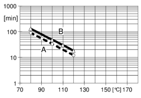
Fig.4.4: Geltime measured with Gelnorm Instrument as a function of temperature
(ISO 9396)
A = 1 pbw DY 061 / B = 0.5 pbw DY 061.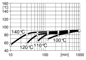
Fig.4.5: Glass transition temperature as a function of the cure time
(isothermic reaction, ISO 11357-2)
Safety & Health
- Industrial Hygiene
- Mandatory and recommended industrial hygiene procedures should be followed whenever the products are being handled and processed.
- First Aid
Contamination of the eyes by resin, hardener or casting mix should be treatedimmediately by flushing with clean, running water for 10 to 15 minutes. A doctor should then be consulted.
Material smeared or splashed on the skinshould be dabbed off, and the contaminated area then washed and treated with a cleansing cream (see above). A doctor should be consulted in the event of severe irritation or burns. Contaminated clothing should be changed immediately.
Anyone taken ill after inhalingvapors should be moved out of doors immediately. In all cases of doubt call for medical assistance.- Handling Precautions
Safety precautions at workplace Protective clothing Yes Gloves Essential Arm protectors Recommended when skin contact likely Goggles/safety glasses Yes Respirator/dust mask Recommended Skin protection Before starting work Apply barrier cream to exposed skin After washing Apply barrier or nourishing cream Cleansing of contaminated skin Dab off with absorbent paper, wash with warm water and alkali-free soap, then dry with disposable towels. Do not use solvents Clean shop requirements Cover workbenches, etc. with light colored paper. Use disposable breakers, etc. Disposal of spillage Soak up with sawdust or cotton waste and deposit in plastic-lined bin Ventilation Of workshop Renew air 3 to 5 times an hour Of workplace Exhaust fans. Operatives should avoid inhaling vapors.
Storage & Handling
- Storage Conditions
The components have to be stored in tightly sealed and dry original containers according to the storage conditions on the product label. Under these conditions, the shelf life will correspond to the expiry date stated on the label. Product specific advise regarding storage can be found on product label. After this date, the product may be processed only following reanalysis. Partly emptied containers should be closed tightly immediately after use.